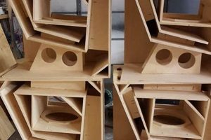
An assembly package designed for individuals to construct their own instrument amplification device offers a hands-on approach to electronics and music technology. These packages typically include all necessary electronic components, such as resistors, capacitors, transistors, and integrated circuits, alongside a chassis, speaker, and detailed instructions for assembly. A typical scenario involves a musician seeking to understand amplifier circuitry while simultaneously creating a customized sound system.
The value of such a project lies in its educational benefit, cost-effectiveness, and potential for customization. Engaging with the internal workings of an amplifier fosters a deeper understanding of audio signal processing. Furthermore, assembling the device independently is generally more economical than purchasing a pre-built commercial equivalent. Historically, this approach has been popular among hobbyists and musicians seeking unique sonic characteristics not readily available in mass-produced amplifiers.
The following sections will delve into specific types of amplification devices suitable for self-assembly, the key components involved, essential tools and safety precautions, and provide guidance on selecting the optimal kit for various skill levels and musical applications.
Essential Guidance for the Aspiring Amplifier Builder
Successfully constructing a personalized amplification system demands careful planning, diligent execution, and adherence to safety protocols. The following guidelines are designed to enhance the building experience and ensure a functional, reliable outcome.
Tip 1: Component Identification is Paramount: Thoroughly identify each component before commencing assembly. Refer to the kit’s schematic and parts list, cross-referencing values and markings to avoid errors. Incorrect component placement can lead to malfunction or damage.
Tip 2: Solder Joint Integrity is Crucial: A robust solder joint is mechanically sound and electrically conductive. Ensure proper heating of both the component lead and the circuit board pad, allowing solder to flow smoothly and create a secure connection. Cold solder joints, characterized by a dull appearance, should be reworked.
Tip 3: Adherence to Schematic Diagrams is Mandatory: The schematic diagram serves as the blueprint for the amplifier’s circuitry. Deviations from the prescribed component placement and wiring configuration can result in non-functionality or, worse, catastrophic failure.
Tip 4: Grounding Techniques Significantly Impact Performance: Proper grounding minimizes noise and interference. Implement a star grounding configuration where all ground connections converge at a single point. This minimizes ground loops, which can introduce hum and unwanted signals.
Tip 5: Voltage Checks are Essential at Each Stage: After completing each section of the circuit, perform voltage checks at key test points. Compare these readings against the expected values outlined in the documentation. Discrepancies may indicate an assembly error.
Tip 6: Enclosure Grounding is a Safety Imperative: The amplifier’s metal chassis must be securely grounded. This provides a path for fault currents to flow to ground, minimizing the risk of electric shock.
Tip 7: Speaker Impedance Matching is Critical: The output impedance of the amplifier must match the impedance of the speaker cabinet. Mismatched impedance can lead to reduced power output, distortion, or damage to the amplifier’s output stage.
These guidelines emphasize the importance of precision, meticulous attention to detail, and a systematic approach to construction. By adhering to these principles, the likelihood of a successful outcome is significantly increased.
The subsequent sections will explore troubleshooting techniques for common amplifier problems, providing a practical framework for addressing potential issues.
1. Components

The selection and understanding of individual components are paramount to the successful assembly and performance of an instrument amplification device constructed from a self-assembly package. The characteristics of each component dictate the amplifier’s tonal qualities, power output, and overall reliability. Careful consideration must be given to the specifications of each element within the circuit.
- Resistors: Current Control and Voltage Division
Resistors limit the flow of electrical current and create voltage dividers within the circuit. Their values, measured in ohms, determine the gain and frequency response of the amplifier. Precision resistors, often metal film types, are preferred in critical signal path locations to minimize noise and distortion. An example is using a specific resistor value to set the bias point of a transistor amplifier stage, directly impacting its headroom and harmonic characteristics.
- Capacitors: Signal Filtering and Energy Storage
Capacitors store electrical energy and block the flow of direct current, allowing alternating current signals to pass. They are used for filtering unwanted frequencies, coupling signals between stages, and providing power supply smoothing. Different capacitor types, such as electrolytic, ceramic, and film, exhibit varying characteristics in terms of frequency response and voltage ratings. Electrolytic capacitors are commonly used for power supply filtering, while film capacitors are favored for signal path applications due to their low distortion characteristics.
- Semiconductors: Amplification and Signal Control
Semiconductors, including transistors and integrated circuits, are the active components that provide amplification and signal control. Transistors can be configured in various topologies, such as common emitter, common collector, and common base, each offering distinct gain and impedance characteristics. Integrated circuits, such as operational amplifiers (op-amps), combine multiple transistors and other components to perform complex functions, such as preamplification and tone shaping. The selection of specific semiconductor devices directly influences the amplifier’s gain, frequency response, and distortion characteristics. For instance, selecting a high-gain transistor for a preamplifier stage will increase the amplifier’s sensitivity, but may also increase noise.
- Transformers: Voltage Transformation and Impedance Matching
Transformers are used for stepping up or stepping down voltage levels and for impedance matching between different circuit stages. In an amplifier, the power transformer converts mains voltage to the required voltage levels for the amplifier circuitry. The output transformer matches the high impedance of the amplifier’s output stage to the low impedance of the speaker. Proper transformer selection is crucial for efficient power transfer and optimal sound quality. An incorrectly sized output transformer can lead to distortion and reduced power output.
These components collectively define the operational parameters of the final device. The careful matching and selection of these parts
within a self-assembly package dictate the characteristics, potential output power, and tone, defining the individual signature of the final product. Neglecting the individual function and interactions between parts will limit the performance of any such project.
2. Schematics

Schematics are an indispensable element of any instrument amplification device self-assembly package. The schematic functions as the visual representation of the electronic circuit, delineating the interconnections between all components. Its accurate interpretation is a prerequisite for successful construction. Any deviation from the schematic’s specifications is likely to cause malfunction or complete failure of the assembled device. As an example, misinterpreting the schematic and incorrectly wiring the power supply section can lead to component damage or potential safety hazards. The schematic, therefore, serves as both a guide and a safeguard.
The significance of the schematic extends beyond basic assembly. Understanding the schematic allows builders to diagnose problems, make modifications, and customize the amplifier’s tonal characteristics. For instance, by studying the schematic, a builder might identify the components responsible for specific frequencies and modify their values to alter the amplifier’s frequency response. Knowledge of schematic reading also enables the selection of appropriate replacement parts should a component fail, contributing to the long-term maintainability of the amplifier. Examining complex schematics, some self-builders even learn enough to create their own designs.
In conclusion, the schematic is the central document for any self-built instrument amplifier, embodying the information necessary for both constructing and understanding the device. Successfully navigating the intricacies of a schematic is crucial for anyone engaging with amplification device self-assembly packages, presenting both a challenge and an opportunity for learning and creative exploration. The availability of clear, accurate schematics directly affects the accessibility and success rate of these projects.
3. Soldering
The process of soldering stands as a cornerstone skill in the successful assembly of instrument amplification devices from self-assembly packages. It establishes the electrical and mechanical connections between components, forming the functional circuits necessary for amplification. Inadequate soldering techniques invariably lead to malfunctions, instability, and potentially catastrophic failures of the finished device.
- Solder Joint Integrity: The Foundation of Reliability
A properly formed solder joint ensures a low-resistance electrical pathway and a robust mechanical bond between the component lead and the circuit board pad. Characteristics of a sound joint include a smooth, shiny surface and a concave shape that indicates proper wetting of both surfaces. Conversely, cold solder joints, characterized by a dull, granular appearance, exhibit high resistance and are prone to failure under stress or thermal cycling. For example, a cold solder joint on a power supply capacitor could lead to intermittent operation or premature component degradation.
- Technique and Tools: Precision in Execution
Effective soldering requires a combination of appropriate tools and precise technique. A temperature-controlled soldering iron, with a tip selected to match the size of the component and pad, is essential. The use of flux, either contained within the solder or applied separately, removes oxidation and promotes wetting. The soldering process involves heating both the component lead and the pad simultaneously, then applying solder to the heated junction, allowing it to flow evenly and create a solid bond. An improperly tinned soldering iron tip, for instance, results in uneven heat distribution and makes creating reliable solder joints difficult.
- Safety Considerations: Mitigating Risks
Soldering involves working with high temperatures and potentially hazardous materials. Adequate ventilation is crucial to avoid inhaling solder fumes, which contain lead and other potentially harmful substances. Eye protection is recommended to prevent accidental splashes of molten solder. Additionally, care must be taken to avoid burns from the soldering iron or hot components. Neglecting to work in a well-ventilated area, for example, exposes the builder to potentially harmful fumes that can lead to respiratory problems.
- Troubleshooting Solder Joints: Identifying and Rectifying Defects
Visual inspection is the primary method for identifying defective solder joints. A magnifying glass or microscope can aid in detecting subtle defects such as cold solder joints, solder bridges (unintended connections between adjacent pads), and insufficient solder. Electrical testing with a multimeter can also help identify high-resistance connections. Defective joints must be reworked by reheating the joint, removing any excess solder, and re-applying fresh solder to create a proper bond. Leaving solder bridges unchecked between component pins, for example, leads to short circuits and improper amplifier function.
Proficiency in soldering is not merely a technical skill but a fundamental requirement for successful engagement with instrument amplification device self-assembly packages. The quality of the solder joints directly determines the reliability, performance, and longevity of the finished amplifier. Neglecting proper soldering techniques ultimately compromises the entire project, highlighting the critical importance of mastering this skill.
4. Safety
The construction of instrument amplification devices from self-assembly packages inherently involves interaction with potentially hazardous voltages and components. Disregard for safety protocols can result in electric shock, burns, or fire. Therefore, a comprehensive understanding and implementation of appropriate safety measures are paramount throughout the entire construction and testing process. Failure to ground the chassis properly, for example, creates a shock hazard should a component within the amplifier short to the chassis.
Specific safety concerns include working with high-voltage power supplies, handling heated soldering irons, and the potential for component explosion if incorrectly installed or subjected to excessive voltage. Mitigation strategies include the use of insulated tools, proper grounding techniques, and thorough verification of component placement before applying power. For instance, reversing the polarity of an electrolytic capacitor can lead to its rapid failure and potentially explosive rupture. Moreover, the final product needs to be enclosed within a grounded metal chassis for protection.
In conclusion, safety is not merely an ancillary consideration but an integral component of any instrument amplification device self-assembly project. Strict adherence to safety guidelines minimizes risks, protects the builder, and ensures the long-term safe operation of the constructed amplifier. Overlooking safety aspects during construction increases the risk of electrical hazards and compromises the overall integrity of the device, ultimately negating the benefits of a DIY project.
5. Cus
tomization

The ability to tailor the characteristics of an instrument amplification device stands as a primary motivation for engaging with self-assembly packages. Customization options range from component selection to circuit modification, each influencing the amplifier’s tonal response and overall performance. The intended effect of customization is a final product uniquely suited to the user’s preferences and musical application. For example, a builder might opt for specific vacuum tubes known for their warm, saturated tone, or incorporate a particular tone stack configuration to achieve a desired equalization curve. This degree of personalization is rarely attainable with mass-produced amplifiers.
The implementation of customization requires a thorough understanding of electronic circuitry and the impact of component values on amplifier behavior. Experimentation with different components, such as capacitors in the tone stack or resistors in the feedback loop, allows for subtle adjustments to the amplifier’s frequency response and gain characteristics. Modifying the bias point of the output tubes, for instance, can significantly alter the amplifier’s clean headroom and distortion characteristics. Furthermore, some kits offer options for incorporating additional features, such as effects loops or variable negative feedback, expanding the amplifier’s versatility. A practical application of customization might involve tailoring the amplifier’s gain structure to better suit a specific guitar’s output impedance, ensuring optimal signal transfer and tonal clarity.
Customization, while offering significant benefits, also presents challenges. Incorrect modifications can lead to instability, reduced performance, or even damage to the amplifier. Therefore, careful planning, meticulous execution, and a thorough understanding of the underlying circuitry are essential. Successful customization yields an instrument amplifier uniquely tailored to the user’s needs and sonic preferences, representing a significant advantage over off-the-shelf alternatives. The understanding of these principles enables the self-builder to transform a standard kit into a personalized instrument.
6. Troubleshooting
The process of troubleshooting is an indispensable aspect of constructing instrument amplification devices from self-assembly packages. Inherent complexities associated with electronic circuitry and component interdependencies invariably lead to challenges necessitating systematic problem-solving. Effective troubleshooting is critical to achieving a functional and reliable amplifier.
- Signal Tracing
Signal tracing involves systematically following the audio signal path through the amplifier circuit, using an oscilloscope or audio probe to identify points where the signal is lost or distorted. This technique is essential for locating faulty components or wiring errors that interrupt the signal flow. For example, if an amplifier exhibits no output, signal tracing can reveal whether the problem lies in the preamp stage, the power amp stage, or the output transformer. Identifying the specific point of signal loss allows for targeted troubleshooting and component replacement.
- Voltage Measurement and Analysis
Voltage measurement and analysis entail verifying the voltage levels at various points within the amplifier circuit using a multimeter. Deviations from the expected voltage values, as specified in the schematic, indicate potential problems such as faulty power supply components, shorted capacitors, or incorrectly biased transistors. For instance, a low voltage reading on a filter capacitor suggests a failing capacitor or a problem with the rectifier circuit. Accurate voltage measurements provide valuable clues for diagnosing circuit malfunctions.
- Component Testing
Component testing involves individually testing electronic components, such as resistors, capacitors, transistors, and diodes, to verify their functionality. A multimeter or component tester can be used to measure the values of resistors and capacitors, and to check the forward voltage drop of diodes. Faulty components, such as open resistors, shorted capacitors, or failed transistors, can disrupt the amplifier’s operation and must be replaced. Identifying and replacing defective components is a fundamental step in the troubleshooting process.
- Visual Inspection and Mechanical Assessment
Visual inspection involves carefully examining the amplifier circuit board for signs of damage, such as burnt components, cracked solder joints, or broken wires. Mechanical assessment includes checking the physical connections of components, ensuring that all wires are properly connected and that there are no loose or shorted connections. For example, a visual inspection might reveal a burnt resistor indicating an overload condition, or a cracked solder joint causing intermittent signal loss. Addressing mechanical issues and correcting visual defects can resolve many amplifier problems.
These facets of troubleshooting collectively provide a framework for systematically diagnosing and resolving problems encountered during the construction or operation of instrument amplification devices from self-assembly packages. Proficiency in these techniques enhances the likelihood of achieving a functional and reliable amplifier, transforming potential setbacks into opportunities for learning and skill development.
Frequently Asked Questions
The following addresses common inquiries regarding the acquisition, assembly, and operation of instrument amplification devices constructed from self-assembly packages. The information provided is intended to clarify aspects relevant to prospective builders.
Question 1: What level of prior experience is required to successfully assemble such a device?
The requisite experience varies depending on the specific kit. Some kits are designed for beginners with minimal electronics knowledge, while others require a more advanced understanding of circuit theory and soldering techniques. Manufacturers typically indicate the skill level required for each kit. Novices should begin with simpler kits featuring clearly documented instructions and pre-assembled components.
Question 2: What are the essential tools needed for assembly?
Essential tools typically include a temperature-controlled soldering iron, solder, wire cutters, wire strippers, a multimeter, and screwdrivers. Additional tools that may prove useful include needle-nose pliers, desoldering braid, and a magnifying glass. Investing in quality tools is advisable to ensure accurate and reliable assembly.
Question 3: What are the potential safety hazards involved, and how can they be mitigated?
Potential safety hazards include electric shock, burns from the soldering iron, and exposure to solder fumes. Mitigation strategies include working in a well-ventilated area, using insulated tools, and adhering to proper grounding techniques. It is crucial to disconnect the device from the power source before making any modifications or repairs.
Question 4: How is the appropriate kit selected for a specific musical application?
The selection process should consider the desired tonal characteristics, power requirements, and speaker configuration. Different kits are designed to emulate specifi
c amplifier types and tonal styles. Researching the specifications of each kit and comparing them to the intended musical application is crucial. Consulting online forums and seeking advice from experienced builders can also provide valuable insights.
Question 5: What are the common troubleshooting steps to resolve issues during assembly or operation?
Common troubleshooting steps include visually inspecting the circuit board for errors, verifying the voltage levels at key test points, and testing individual components. Signal tracing with an oscilloscope or audio probe can also help identify faulty sections of the circuit. Consulting the kit’s documentation and seeking assistance from online communities are valuable resources for troubleshooting.
Question 6: What degree of customization is possible with these devices?
The degree of customization varies depending on the kit design and the builder’s skill level. Some kits offer options for component substitutions and circuit modifications, allowing for adjustments to the amplifier’s tonal characteristics and performance. Advanced builders may even design their own modifications, expanding the amplifier’s capabilities. However, it is important to note that incorrect modifications can lead to instability or damage.
These frequently asked questions address common concerns related to the construction and utilization of these self-assembled devices, with answers intended to promote understanding and safe practices.
The subsequent section will provide a summary of the benefits and drawbacks of instrument amplification device self-assembly packages.
Concluding Remarks on DIY Guitar Amp Kits
The preceding exploration detailed the diverse aspects of the self-assembly instrument amplifier, from fundamental components and schematic interpretation to soldering techniques, safety protocols, customization possibilities, and troubleshooting strategies. The decision to engage with a diy guitar amp kit demands a commitment to precision, a dedication to learning, and an acceptance of inherent challenges. Successful completion offers not only a functional amplification device but also a deeper understanding of electronic circuitry and audio engineering principles.
The construction of a personalized amplifier is an undertaking that merges technical skill with artistic expression. Whether motivated by cost savings, a desire for sonic customization, or a pursuit of knowledge, prospective builders should approach the project with diligence and respect for the inherent complexities. Continued advancement in component availability and design resources promises to further enhance the accessibility and sophistication of these self-assembly projects, ultimately fostering greater innovation within the musical instrument amplification domain.